Frame with Irregular Sized Timber
Most large timbers that are sawn for framing never make it to a 4-sided planer. Even with an experienced sawyer and a top-notch mill there will be variation in the cross-sectional sizing of the timbers. When the framer begins to build with these irregular timbers, it’s imperative that there is a good understanding of the fundamentals of laying out rough sawn timber.
The challenge is that you want to construct a building that is a given dimension wide x long x high. with material that is not consistent. There are a few different ways to handle this. Having some basic understanding of carpentry will be extremely helpful with this endeavor.
However, if you have that, we are confident we can get your started out on the right foot with this instruction, through our joint library, and our square rule plan that is geared towards instruction.
Table of contents
Square Rule Method
Find the “perfect” timber inside
One approach that we know well and have used with great success is the square rule method. Quite simply the square rule method is based on the principle of finding a “perfect” timber inside an imperfect one. This basically refers to finding for example, a timber cross section that may be 7 ¼” x 7 ¼” inside 8×8 timbers that vary from one to the next. We would call this working to ¾” Under Nominal. Once you understand what the goal is here with sizing, we then introduce how to get there with the reference plane principle.
Reference Planes
Even if you have perfect s4s timbers (surfaced 4 sides) good timber frame construction practice is to always work (or begin your dimensions) from the proper datums, or origins. Logically if you plan to build a rectangle on top of rectangular foundation, then the most critical dimensions that your varying timber should meet, are the outside length x width of the frame.
Therefore, the outside faces of your timber posts and plates need to be the references for the layout of the rough sawn timber. If you have 4 posts going down a wall, and all of those posts vary in size, you will at least have the outside faces be in a common plane, but the inside faces will not!
This same logic that determines that the outside of the structure should be a reference plane leads you to understanding that the top of top plates and ridge beams should be reference faces, or planes, too.
Drawing Diagrams for Reference Planes
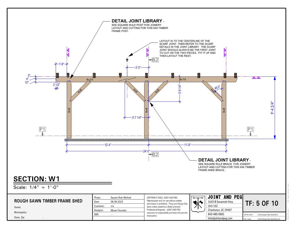
We assign the reference planes in our drawings and always represent them with the double triangles that are purple in color drawings and just black in black and white drawings.
We realize that trying to teach this method is very difficult in words, so we have made drawings! You can visit our joint library and look up rough sawn joints. Also,, we suggest considering a purchase of our Rough Sawn Timber Frame Instruction Plan that goes into all of this in detail with extensive notes in the drawings. Further you get a wonderful 14×24 shed roof timber frame as a conclusion of working through it!
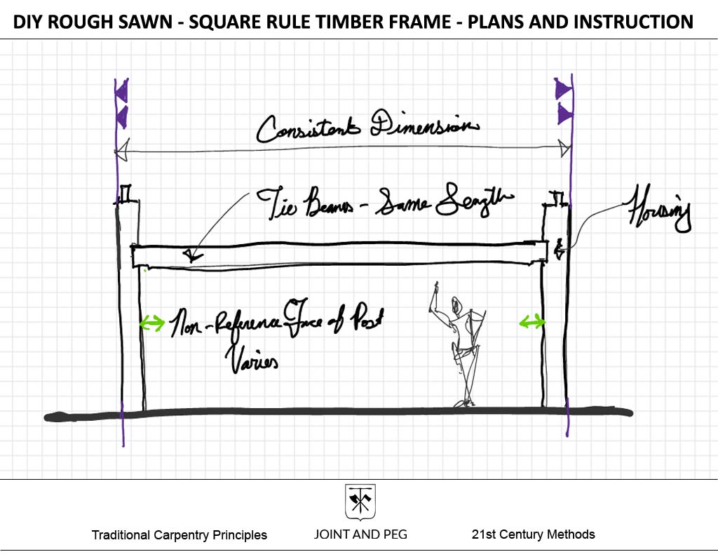
So again, with reference planes, you will always pull your measurements from those, and the variation of the timber sizing will be left on the non-reference side (the opposite).
It’s important to note that sometimes reference planes are better suited as centerlines that are represented as chalk lines on the timbers. But that’s for later. This edge referencing will work just fine for now.
Square Rule Housings
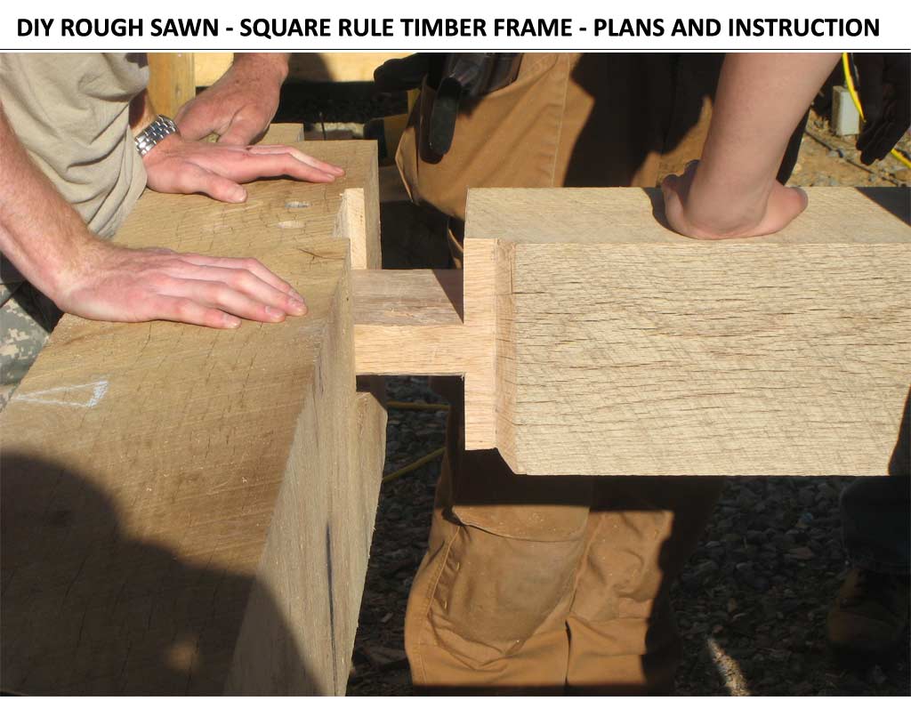
Ok, so you got the idea of the reference plane! Wonderful. Your next question should be, “But how do we get to the perfect timber on the non-reference side that varies?” The answer is Housings! Housing in a timber frame can serve as spots where tremendous loads bear from beams to posts, but they can also double as ways to find the “perfect” timber.
Think of it this way you are building a structure with a bent that consists at the lower level of 2 posts, 2 braces, and a tie beam. Actually, let’s leave the brace out for the moment. Once you get this understanding of the beam and posts you can go learn about the knee braces in a square rule frame.
Ok, so if we have four bents in this structure, with (8) posts that vary in size, the last thing we want to do is have (4) tie beams that vary in length! You understand why right? There should be no varying in length of common members! This would be an unpleasant experience.
Allows for Common Length Members
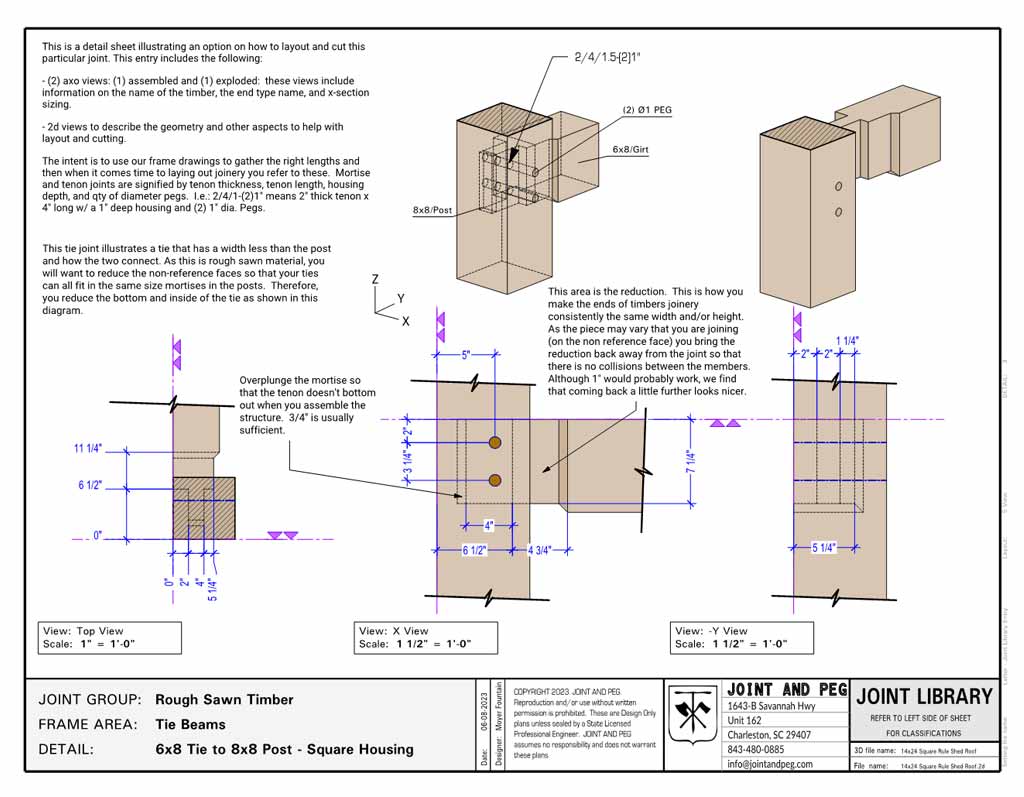
Think of it (4) tie beams that vary in lengths of less than an inch or so. No good! But if you measured, say 6 ½” off of the outside of the post (reference plane again) to the housing where the end of the tie beam rests; then you have a good common measurement to use for all the other posts.
Theoretically, this housing would be 1 ½” deep for an 8×8 post but remember it will vary slightly because the post sizes are different in cross section. So, to conclude this idea: with (8) posts that vary in width (4 on each side) oriented on their reference planes (see purple triangles) we now have the ability to create (4) tie beams of all equal length be measuring 6 ½” off the reference for all the posts.
Got it? Great!
Reductions or “Gains”
If you have followed along so far, we know understand how to accomplish creating common members with the same length that join into irregular cross sections. That’s great but there is one little other area to consider. Just as much as don’t want to have different length common members, we also don’t want to have different length housings and mortises to accept those members.
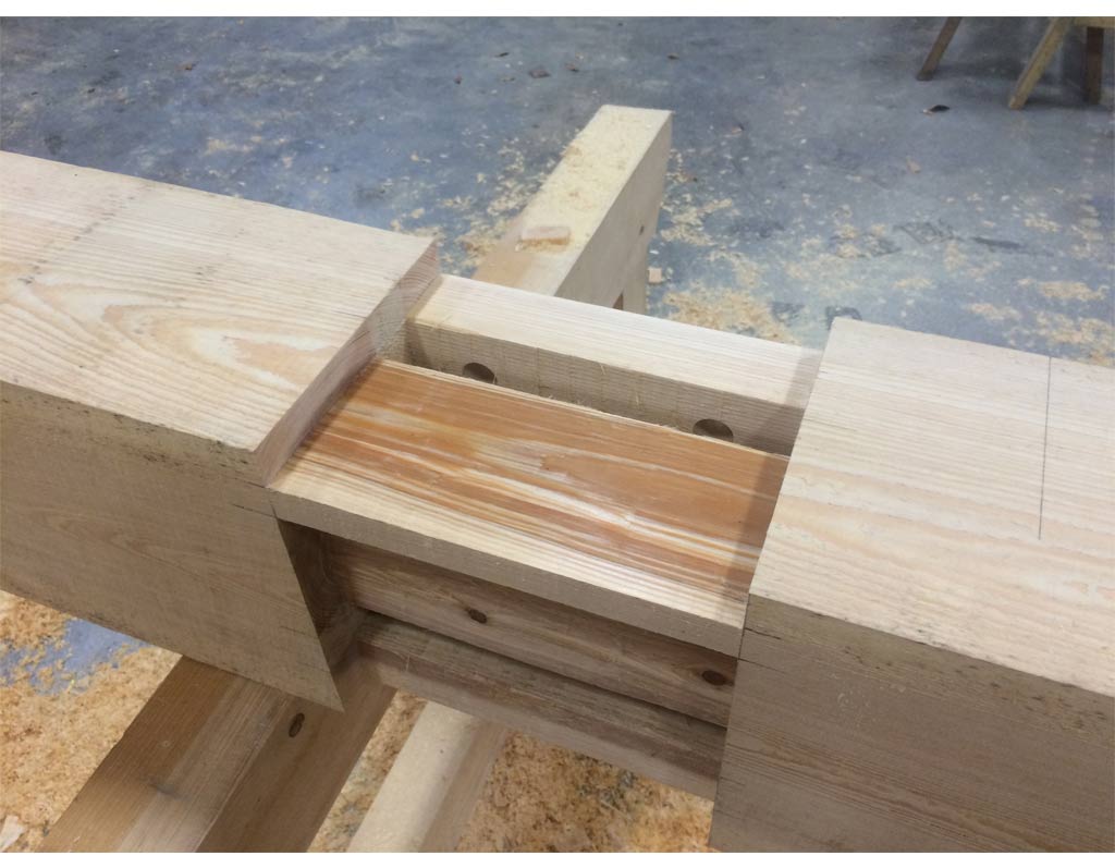
Take a look at our tie beam housing arrangement in the post. Our tie beam is going to vary in cross section too! Well, we need to reduce it so we can have common housing on that post. Let’s do this, let’s work to ¾” Under Nominal and reduce say an 8×10 tie beam to 9 ¼” in height.
If we do that, we can now have common housing and mortise on all the posts to accept the tie beams!
Lastly, we need to make the reduction go further along the tie beam than the potential variation of the post non-reference face. Otherwise, we could have a collision when the joint is assembled. As much as I’d like to write further about this method, I think it would serve us better to look at a drawing of that detail here of a 6×8 Tie.
Conclusion
Hopefully with any luck you have now learned the basics of square rule framing with rough sawn timber. There is still more to learn in the way of braces but I think that the underlying principles have been addressed. We recommend that you go to our Connection Library for further study.
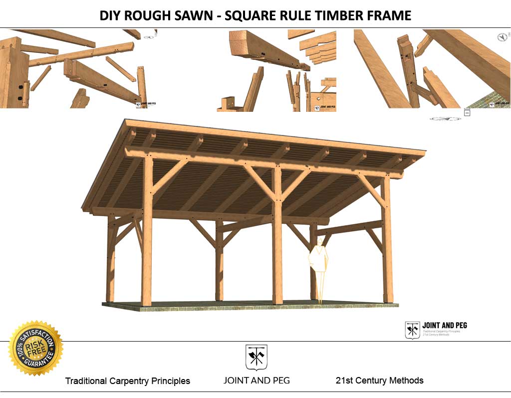
If you feel you are ready to attempt the construction technique, we have our Rough Sawn Instruction Plan that provides you with more learning and instruction while providing a sweet shed roof timber frame structure!
Rough Sawn Timber Frame Instruction
The most extensive plan available that instructs on the fundamental methods of timber framing with rough sawn timbers. Build this shed roof structure and learn square rule as you go. Almost all the extras are already included in this plan! Why not have a great carport and take your carpentry skills to the next level?
Looks like a lot of great information and useful advice. I plan on looking deeper into this and will let you know how my experience goes!
Happy to hear that Richard! Best of luck with the frame!