Starting off with the standard timber frame joints. Here we have the three main joints you will come across in a timber frame structure. Please note the descriptions we have for these areas as we talk about tenon thickness, mortise depths, peg layout, and many other key elements of craftsman style joinery of timbers.
Table of contents
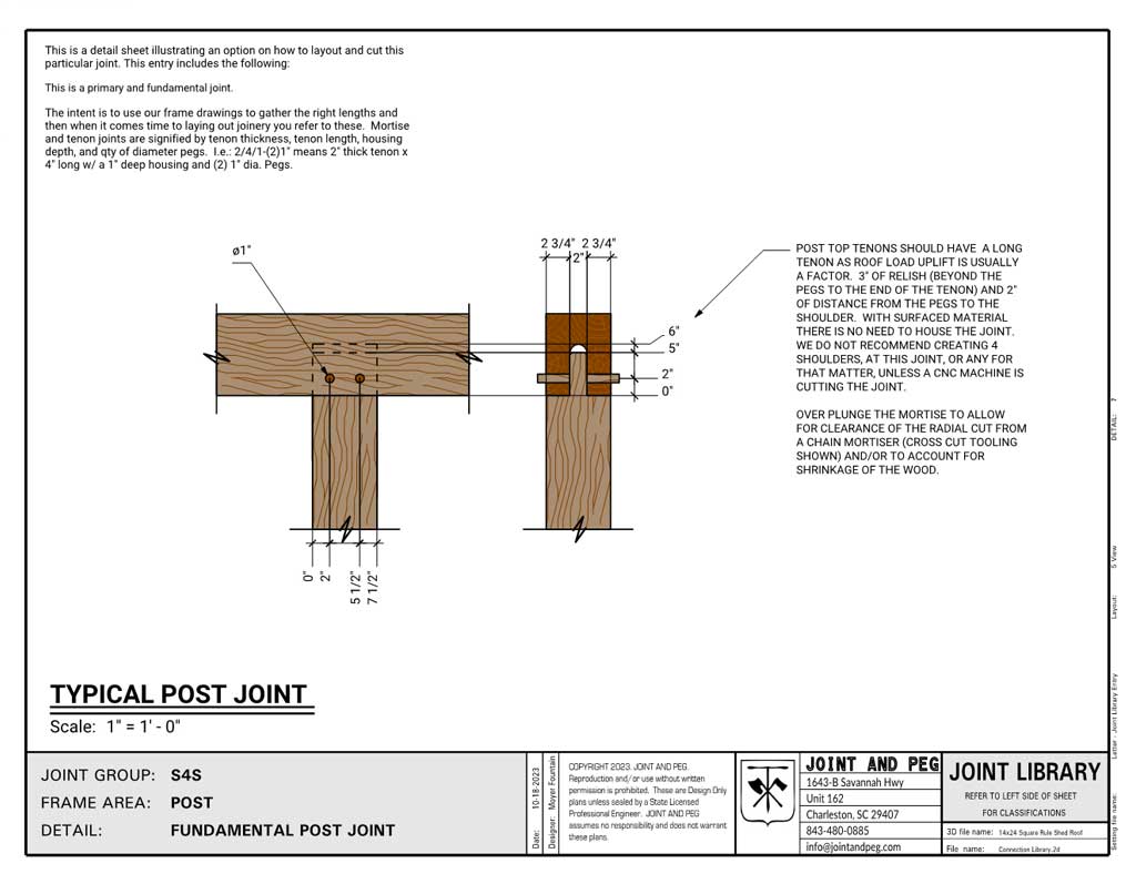
Standard Post Joint
The first standard timber frame joint. Post top tenons should have a long tenon as roof load uplift is usually a factor. 3″ of relish (beyond the pegs to the end of the tenon) and 2″ of distance from the pegs to the shoulder. With surfaced material there is no need to house the joint. We do not recommend creating 4 shoulders at this joint, or any for that matter, unless a cnc machine is cutting the joint.
Over plunge the mortise to allow for clearance of the radial cut from a chain mortiser (crosscut tooling shown) and/or to account for shrinkage of the wood.
There are other scenarios where post bottoms and tops can have different connections and detailing.
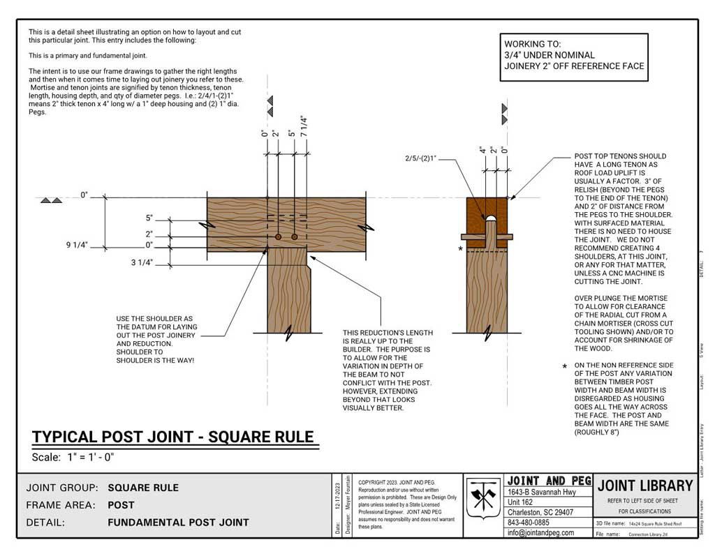
Standard Square Rule Post Joint
Using the square rule method, here is the standard detail for a rough sawn timber frame post top. The reductions and use of proper reference planes to layout and cut the work allows this system to excel when dealing with varying cross section timber sizes.
See more information on working with rough sawn material and the square rule method.
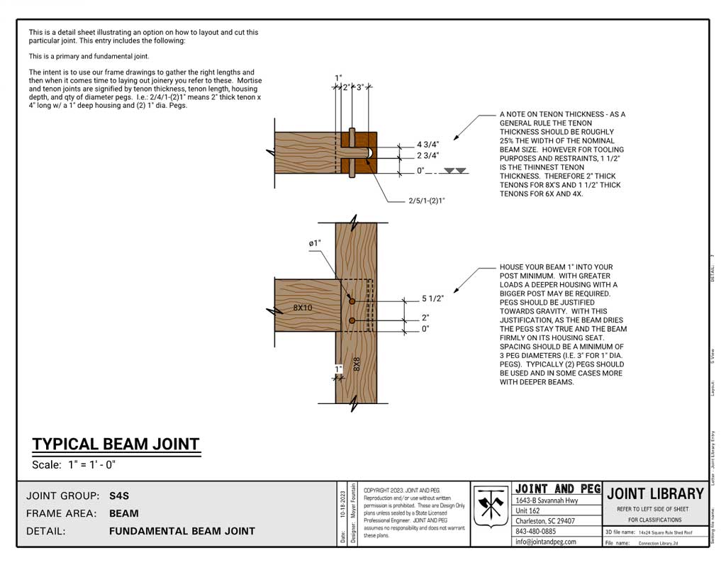
Standard Beam Joint
House your beam 1″ into your post, minimum. With greater loads a deeper housing with a bigger post may be required. Pegs should be justified towards gravity. With this justification, as the beam dries the pegs stay true and the beam firmly on its housing seat. Spacing should be a minimum of 3 peg diameters (i.e. 3″ for 1″ dia. Pegs). A standard timber frame joint for a tie beam should include (2) pegs minimum, and in some cases more with deeper beams.
A note on tenon thickness – as a general rule the tenon thickness should be roughly 25% the width of the nominal beam size. However, for tooling purposes and restraints, 1 1/2″ is the thinnest tenon thickness. Therefore 2″ thick tenons for 8x’s and 1 1/2″ thick tenons for 6x and 4x.
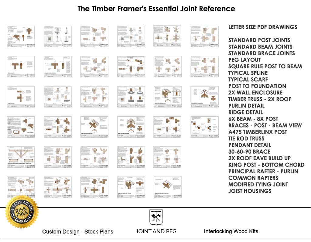
Timber Frame Joint Details Catalog
Stop guessing your joinery dimensions. Build from professional construction details developed through decades of timber framing experience.
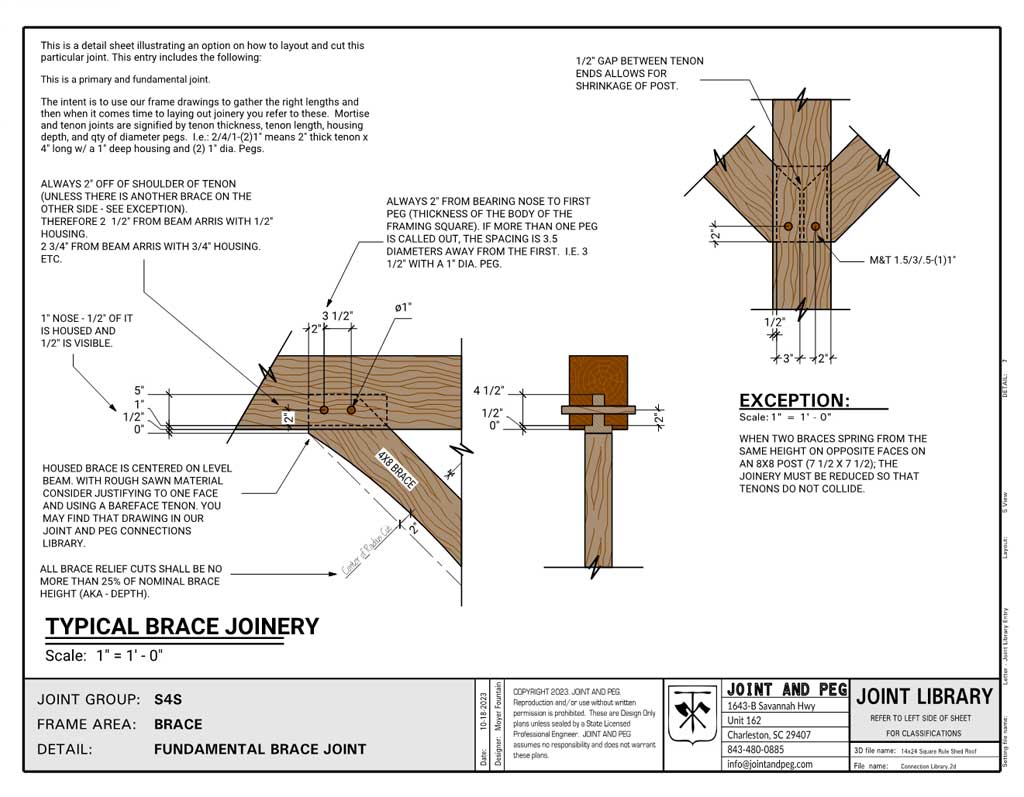
Standard Knee Brace Joint
For peg layout along the beam, measure 2″ from bearing nose to first peg (thickness of the body of the framing square). If more than one peg is called out, the spacing is 3.5 diameters away from the first. I.e. 3 1/2″ with a 1″ dia. Peg.
For peg layout up and down the face of the beam, measure 2″ off of shoulder of tenon (unless there is another brace on the other side – see exception).
Therefore 2 1/2″ from beam arris with 1/2″ housing. 2 3/4″ from beam arris with 3/4″ housing. Etc.
Using bare face tenons with only one shoulder is a good option when producing braces in rough sawn stock.
Peg Locations for Timber Frame Joint
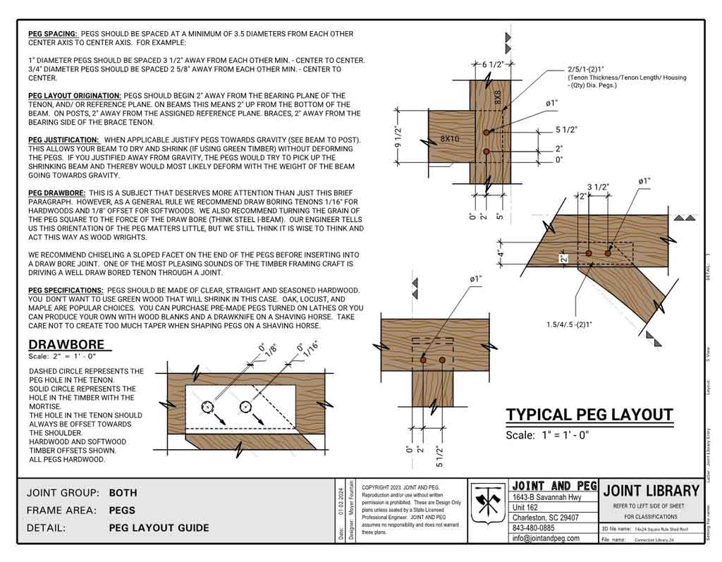
Peg Spacing
Pegs should be spaced at a minimum of 3.5 diameters from each other center axis to center axis. For example:
1″ diameter pegs should be spaced 3 1/2″ away from each other min. center to center.
3/4″ diameter pegs should be spaced 2 5/8″ away from each other min. center to center.
Datums
Pegs should begin 2″ away from the bearing plane of the tenon, and/ or reference plane. On beams this means 2″ up from the bottom of the beam. On posts, 2″ away from the assigned reference plane. Braces, 2″ away from the bearing side of the brace tenon.
When applicable justify pegs towards gravity (see beam to post). This allows your beam to dry and shrink (if using green timber) without deforming the pegs. If you justified away from gravity, the pegs would try to pick up the shrinking beam and thereby would most likely deform with the weight of the beam going towards gravity.
Drawbore
This is a subject that deserves more attention than just this brief paragraph. However, as a general rule we recommend draw boring tenons 1/16″ for hardwoods and 1/8″ offset for softwoods.
We also recommend turning the grain of the peg square to the force of the draw bore (think steel i-beam). Our engineer tells us this orientation of the peg matters little, but we still think it is wise to think and act this way as wood wrights.
We recommend chiseling a sloped facet on the end of the pegs before inserting into a draw bore joint. One of the most pleasing sounds of the timber framing craft is driving a well draw bored tenon through a joint.
Wood Species
Pegs should be made of clear, straight and seasoned hardwood. You don’t want to use green wood that will shrink in this case. Oak, locust, and maple are popular choices.
You can purchase pre-made pegs turned on lathes or you can produce your own with wood blanks and a drawknife on a shaving horse. Take care not to create too much taper when shaping pegs on a shaving horse.
Diminished Housings
Diminished housings are generally used when the member being housed is oriented flush to one face (as in the case of narrow brace meeting a bigger post or beam), or when the housed member is the same width as the receiving beam (8x tie beam into 8x post).
We like them as they can be easier to cut, especially with the latter example stated above, and that they can provide easier layout when working with irregular timbers.
